Foundations Episode #20 – Scaling Scanning

Foundations Episode #20 – Scaling Scanning

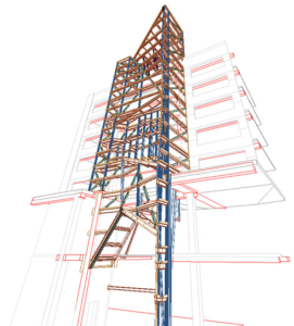
Scanning has become an important part of the DBO process, and construction companies large and small are using this powerful technology on projects of all sizes. In this episode of Foundations, we’re joined by Tim Malys from DPR Construction, to discuss how they’ve been using scanning for their projects.

2017-08-04T09:00:07-04:00August 4th, 2017|BuildBlog, Foundations|

Register for next month’s Trimble MEP user conference

Register For Next Month’s Trimble MEP User Conference

Join hundreds of industry leaders from around the world for 2.5 days and over 100 informative sessions, technical training, labs, demos and support one-on-one sessions. From this exciting event, you will be equipped with the knowledge you need to overcome challenges faced in today’s competitive MEP business environment.

2017-08-03T10:30:08-04:00August 2nd, 2017|BuildBlog|

One Stop Cost Estimating

One Stop Cost Estimating

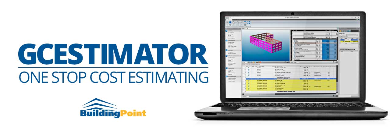
Today, there are two different paths for construction cost estimating. You have the option of utilizing either 2D plans, or 3D models. The decision as to which method will be chosen for the pre-construction and estimating phase traditionally rests upon two factors. The requirements of the bid and the constraints placed by the owner, and the overall familiarity and comfort with detailed (or not-so-detailed) BIM models. This is a reasonable criteria. Construction companies have a tried and true 2D estimation process based upon years of experience, best practice, and real-world historical actuals. This data set consistently provides the most comprehensive and reliable estimation baseline, while 3D models typically provide a greater level of detail and quantity information.

So the question remains… Why don’t we combine the two? Trimble has answered this question with GC Estimator. Now, we can. With GC Estimator, you can seamlessly integrate custom assemblies and actual quantity pricing with 3D models and quantities, giving you a hybrid solution that is head and shoulders above the estimate provide by standalone 2D or 3D data.

To learn more about GC Estimator, or to view an in-depth demo, simply click the link below.

2017-08-03T10:30:09-04:00July 31st, 2017|BuildBlog|

How Much Accuracy Is Enough?

How Much Accuracy Is Enough?

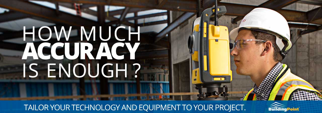
Following up on the blog post from earlier this week, we’re revisiting the concept and the idea of accuracy on a construction project. Every job is different. And a variety of different inputs and constraints dictate the tolerances for a particular scope within a particular project. The possibilities are endless. But often times, users get caught up looking at the accuracy of a particular instrument, total station, or scanning solution and see that as a gating item for job site integration. Without a doubt, some projects have very tight tolerances. Understanding the capabilities and limitations at the solutions in your toolkit can go a long way towards ensuring that project accuracy goals and tolerances are met. In this post, let’s take an (admittedly) brief look at the concept of angle accuracy, specifically when it comes to robotic total stations.

The accuracy of an optical instrument is represented as something called “angular accuracy”. This means how small of an angle the instrument can measure. This accuracy is measured in “seconds”, or arc seconds. In radial measurements, we assume that there are 360 degrees in a circle. Taken a step further, you can divide each degree into 60 equal parts, or “minutes”. Taken one step further, you can divide these minutes into 60 equal parts or “seconds”.

Given that optical instruments (typically mechanical and robotic total stations) are categorized based on their angular accuracy, which we measure in arc seconds. We are defining the differences in 1/3600th of a degree increments. That’s a very, very tight tolerance. Most commercially viable total stations provide measurements with 1, 3, or 5 second accuracy. That’s 1/3600, 1/1200, or 1/720 of a degree, respectively. How does this look in the real-world? Let’s take a look.

First, let’s take a look at 200’. In most vertical buildings, this is a fairly long run from a station. In this scenario, the tolerance for 1, 3, and 5 second accuracies would be:

< 1/64” for a 1 second instrument
< 3/64” for a 3 second instrument
< 1/16” for a 5 second instrument

Now, let’s move closer. At 100’ from the instrument, the tolerance increases to:

< 1/128” for a 1 second instrument
< 3/128” for a 3 second instrument
< 1/32” for a 5 second instrument

And finally, let’s move closer, to 50’ from the station. Given the realities of construction, 50’ is the baseline average because of obstacles, equipment, and structural elements that block line of sight.

< 1/256” for a 1 second instrument
< 3/256” for a 3 second instrument
< 1/64” for a 5 second instrument

As we can see from these calculations, the angular accuracy of the optical instrument does not significantly impact the measurement accuracy and tolerance a specific point. Now, as distance increases, it most certainly begins to impact accuracy, in a logarithmic fashion. So for significantly long runs, or for very long control runs, it does impact accuracy. But within a building project, the optical instrument is typically well within the margin of error when it comes to accuracy and tolerance.

By understanding angular accuracy, you can begin to tailor your technology and equipment to match the requirements of your project. Saving both time and effort.

2017-08-03T10:30:09-04:00July 27th, 2017|BuildBlog|

Connect & Go : Quick And Easy Layout With GNSS

Connect & Go : Quick And Easy Layout With GNSS

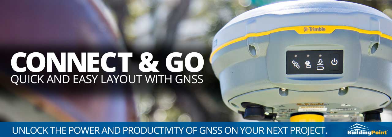
We often talk about Building Construction in the tightest tolerances possible. In most cases, the more accurate the better. With robotic total stations, the XYZ tolerance can be 1/16”, or .0625” for those of us in the decimal system. And while there is certainly something to be said for amazing accuracy… sometimes it doesn’t have to be that tight. To reach that level of accuracy on a layout project, robotic total stations must utilize on-site control to reference the total station’s position and orientation on the project. But what if no on-site control exists? Or, what if that control is suspect to begin with? Enter satellite-based solutions, such as the Trimble R8s.

With a networked solution such as the Trimble R8s, you can simply pull the receiver out of the case, dial into the Trimble VRSNow network, and begin laying out and checking points and control locations. To be sure, the level of accuracy is not identical to a robotic total station solution, but in most cases you can achieve real-time accuracy of less than 1”. This tolerance is more than acceptable for checking forms, building edges, site boundaries, and a myriad of other early production tasks.

To learn more about the Trimble R8s, you can simply click the link below.

2017-08-03T10:30:09-04:00July 25th, 2017|BuildBlog|

Foundations Episode #19 – Lessons Learned

Foundations Episode #19 – Lessons Learned

Webster’s dictionary defines coordination as “ the process of organizing people or groups so that they work together properly and well.” At face value, it sounds simple but in construction, we know that can be challenging. In this episode, we’re joined by Ali Clutter, a Project Manager from the Tampa Area, to talk about coordination, specifically the differences between traditional coordination and using VDC models.

2017-07-21T10:11:02-04:00July 21st, 2017|BuildBlog, Foundations|

Scanning As A Snapshot

Scanning As A Snapshot

In numerous previous posts, BuildingPoint has discussed the value of laser scanning to deliver a truly accurate “snapshot” of a project. Typically, this capability is discussed within the scope of an entire project or proposed project. But it’s also important to remember that these powerful capabilities can be delivered within a smaller scope. Problem areas, regions with significant as-built deviations, detailed elements, and even issues limited to specific floors or disciplines.
Traditional laser scanning offers a fantastic option in these particular instances.

When leveraging static scanning solutions such as the Trimble TX6, you can quickly and easily focus on the particular area of interest. Specific use cases, such as the integration and coordination of structural steel that has already been placed with downstream finishing materials, or tying to existing mechanical or electrical systems can easily be achieved with just a couple of scan stations. This means that you can gain a complete 3D representation of your existing conditions in 15 minutes or less. The resulting data set can then be fed into your design or coordination software to identify issues before they become change orders.

With the Trimble TX-series of laser scanning solutions, you can make decisions based on actual and meticulously detailed point cloud data captured from the field.

2017-08-03T10:30:09-04:00July 19th, 2017|BuildBlog|

Seamless Integrations With Trimble Connect

Seamless Integrations With Trimble Connect

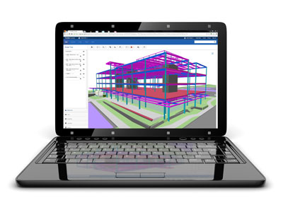
With Trimble Connect, construction professionals and stakeholders finally have a simple, easy-to-use, and intuitive platform for sharing ideas and information on projects of any scope or size. More than just a file sharing application, Trimble connect is a truly modern platform that takes care of the heavy lifting, allowing teams to collaborate with models or plans in a responsive and open web-based environment.

And while the capabilities of Trimble Connect are robust in and of themselves, a significant amount of power is available through the seamless integrations that are interwoven into the very fabric of Connect. With these integrations, users can leverage their existing applications and workflows, while realizing the benefits of operating within a completely sharable cloud-based environment. Today, Trimble offers a number of powerful integrations, several of which are briefly outlined below.

Trimble Prolog: When integrated with Trimble’s powerful project controls solution, Trimble Connect allows users to easily view 3D models. This visibility enables a powerful capability to view RFI’s, change orders, or any other number of open items within the context of the federated project model.

Autodesk Revit: Publishing a .rvt model to Trimble Connect couldn’t be easier. With a simple Trimble Connect add-in users can enable simple one-click publishing that streamlines the process to share a model in Trimble Connect, without ever leaving the application.

Field Layout: Publishing models to the cloud is certainly a powerful capability, but with Trimble Connect and Trimble Field Link, you gain the all-important round trip functionality as well. With this solution, you can easily send layout files from the office to the field. Then, once field layout has been completed, field personnel have the ability to publish their results back to Trimble Connect, giving real-time feedback to office personnel looking to review and update model geometry with real-world conditions.

To learn more about Trimble Connect, and the powerful integrations that are available today, simply click the link below. Welcome to a collaboration environment where you and everyone involved in your construction project knows what’s happening now. And what should be done next.

2017-08-03T10:30:10-04:00July 14th, 2017|BuildBlog|
Go to Top